Thursday, November 28, 2013

Alliant RT2S RT2V Operation, Maintenance & Parts Manual

http://www.industrialmanuals.com/alliant-rt2s-rt2v-operation-maintenance-parts-manual-p-22.php

Alliant RT2S RT2V Operation, Maintenance & Parts Manual 
 
 Alliant RT2S RT2V Vertical Milling Machine Operation, Maintenance & Parts Manual.

This Manual Covers: I.M. Inventory # A-164A
Table of Contents 
Foreword.
Warranty
Safety
RT 2S Main Machine Features
RT 2V
Basic Machine Dimension
Head Dimensions

Variable Speed Head Dimensions
Machine Specifications
Uncrating and Installation
Level the Machine
Proper Method for Lifting Machine
Head Alignment
Align Y Axis
Align X Axis
Standard Head
Swivel Belt Housing
Spindle Brake
Changing Spindle Speed
Changing Drives
Belt Replacement
Replacing the Brake Block on the Standard Milling Head
Variable Speed Head
High and Low Range Switch
High-Neutral-Low Lever
Automatic Quill Feed Engagement
Feed Rate Selector
Feed Reversing Knob
Quill Depth Stop
Micrometer Depth Control
Quill Locking Lever
Handwheel Feed Control
Automatic Feed
Spindle Brake
Collet
Feed Trip Adjustment
Collet Aligning Screw Replacement
Swivel Belt Housing
Changing Spindle Speed
Changing Drives
Motor Removal
Timing Belt Replacement
Drive Belt Replacement
Replacing the Brake Shoes on the Variable Speed Head

Electrical Diagram
Preventive Maintenance

Parts Information
Base Machine Assembly Parts
 Illustration
Standard Head Assembly Parts
 Illustration (Plate 2)
Variable Speed Head Assembly Parts List Illustration
Variable Speed Pulley Parts List
 Illustration (Plate 4)
Quill Feed Assemblies & Parts 
Quill Feed
 
Engagement Assembly Parts List
 Illustration (Plate 6)
Hi-Neutral-Low Assembly Parts List 1 -7
Hi-Neutral-Low Assembly Illustration (Plate 7)
Quill Locking Assembly Parts List
Quill Locking Assembly Illustration (Plate 8)
Brake Handle and Brake Shoe Assembly Parts List 1 -8 Brake Handle and Brake Shoe Illustration (Plate 8)
Head Tilting Assembly Parts List 1 -9 Head Tilting Assembly Illustration (Plate 9)
Brake Block Assembly Parts List 1 -10 Brake Block Assembly Illustration (Plate 10)
Brake Handle and Brake Finger Assembly Parts List 1 -
11
 Illustration (Plate 11)
Motor Locking Assembly for Standard Head 2 HP Parts List 1 -12
Motor Locking Assembly for Standard Head 2 HP Illustration (Plate 12)
Ram Lock Assembly Parts List 1 -13  Illustration (Plate 13)
Longitudinal Screw Assembly Parts List 1 -14
 Illustration (Plate 14)
Saddle Gib and Clamping Assembly Parts List  1-15
 Illustration (Plate 15)
Elevating Screw Assembly Parts List 1 -16
 Illustration (Plate 16)
Knee Gib and Wiper Assembly Parts List 1 -16
 Illustration (Plate 16)
Knee Locking Assembly Parts List 1 -17 
Illustration (Plate 17)

It has about 58 pages

Allen No. 3, V-Belt Vertical Drilling and Tapping Machine, Operations Manual

http://www.industrialmanuals.com/allen-vbelt-vertical-drilling-tapping-machine-operations-manual-p-2561.php 


Allen No. 3, V-Belt Vertical Drilling and Tapping Machine, Operations Manual 

Allen No. 3 V-Belt Vertical Motor Drive, Drilling and Tapping Machine, Operator and Maintenance Manual Year (1979)                

This Manual Covers Models: 
No. 3
Type VC-VCDW-VCCF-VCT
This Manual Includes: 

Safe Operation
Installation
Lubrication
Operation of Drives
Operation Of Sliding Heads:
hand Feed Sliding Head
Semi Auto Tapping
Lead Screw Tapping, Diagram of Controls and Trouble Shooting
Drop Worm Power Feed
Repair Parts Diagrams and Lists
Safety Suggestions
Machine Control locations
General Specifications
Cutting Speeds and Feeds
Adjusting the Ten Speed Drive - Diagram

This Manual Has  27 Printed Pages.
Year June 1979

Allen No. 3 & No. 3V Drilling Tapping Parts Manual

http://www.industrialmanuals.com/allen-drilling-tapping-parts-manual-p-403.php

Allen No. 3 & No. 3V Drilling Tapping Parts Manual 

Allen No. 3 & No. 3V Drilling Tapping Parts Manual


This Manual Covers Models:

No. 3

No. 3V


This Manual Includes:

Parts


This manual is about 29 pages

Sunday, November 24, 2013

Allen No. 2, Motor Spidnel & Drive, Drilling & Tapping Parts Manual

http://www.industrialmanuals.com/allen-motor-spidnel-drive-drilling-tapping-parts-manual-p-2770.php 


Allen No. 2, Motor Spidnel & Drive, Drilling & Tapping Parts Manual 

Allen No. 2, Motor Spindle & Drive, Drilling & Tapping Parts List Manual                 

This Manual Covers Models: 
No. 2

This Manual Includes:
How to Order Parts
Machine View
Index
Parts Lists
Functional Illustrated Drawings Showing Component Identification
This Manual Has  64 Printed Pages

Allen No. 2 & 2 1/2, Drilling & Tapping, Operations & Maintenance Manual 1979

http://www.industrialmanuals.com/allen-drilling-tapping-operations-maintenance-manual-1979-p-2769.php 


Allen No. 2 & 2 1/2, Drilling & Tapping, Operations & Maintenance Manual 1979 

Allen No. 2 & 2 ½, Drilling & Tapping, Operations & Maintenance Manual Year (1979)                 

This Manual Covers Models: 
No. 2
No. 2 ½
Types MA-MADW-MACF
MAT-MAV-MAVDW
MAVC-MAVT

This Manual Includes:
Safe Operation
Installation
Lubrication
Operation of Drives
Operation of Sliding Heads
Safety Guide Lines
Machine Control Locations
General Specifications
Cutting Speed and Feeds
Introduction
Extra Assemblies:
Feed gear Assembly
Parts List
Cam Feed With Positive Clutch Control Sliding Head and Spindle Assembly

This Manual Has
 31 Printed Pages.
Year March 1979

Allen No. 2 & 2 1/2 Drilling Tapping Parts Manual

http://www.industrialmanuals.com/allen-drilling-tapping-parts-manual-p-402.php

Allen No. 2 & 2 1/2 Drilling Tapping Parts Manual 

Allen No. 2 & 2 1/2 Drilling And Tapping Machine Parts Manual 


This Manual Covers Models:

No. 2

No. 2 1/2


This Manual Includes:

Parts


This manual is about 50 pages

Friday, November 22, 2013

Allen braley Original Block Diagrams System 7365, J&L "A Line" Control Manual

http://www.industrialmanuals.com/allen-braley-original-block-diagrams-system-7365-line-control-manual-p-2587.php 


Allen braley Original Block Diagrams System 7365, J&L "A Line" Control Manual 

Allen Bradley Original Block Diagrams System 7365, J&L A Line Control Manual Year (1978)       

This Manual Covers Models:
System 7365
J&L A Line Control

This Manual Includes: 
Part Nos. and Mnemonic Code Columns Also Carry Tile of Block Drawing
Specifications
Processor Rack Mother Board
Input/Output Rack Motherboard
Industrial Processsor Panel
Interface Submodule
Industrial Processor Memory, 8K Increment
Industrial Processor Memory, 4K Increment
Memory Interface
Processor Panel Interface
Micro Control
Arithmetic Logic Unit
Input/Output Multiplexer Interface
CRT and MDI interface
Tape Reader/Punch Interface (RS-408-)
32 Bit Input Module
Floppy disc Interface Module
Combined Axis Module Resolver
Feedback with DC Drive
Combined Axis Submodule
115 VAC Solenoid Driver Module
Indicator Module
Input/Output Rack Adapter Module
Maint Power Supply Control
Maint Power Supply Regulator
Maint Power Supply distribution and Filter
Memory Power Supply
Main Power Supply Schematic
Memory Power Supply Assembly Print
Power distribution
Memory Battery
Cable-Processor
Power Supply Cable Assembly
Memory Power Supply Cable Assembly
I/O Adapter Cable Assembly
I/O Power Supply Cable Assembly
Memory Power Supply AC Cable Assembly
Cable Power Supply Input Assembly
Battery Cable Assembly
Power Supply Schematic and Assembly
This Manual Has 236 Printed Pages.
Year September 1978

Allen Bradley SLC100 Programmable Controller 1745 Processor Unit Manual

http://www.industrialmanuals.com/allen-bradley-slc100-programmable-controller-1745-processor-unit-manual-p-1763.php 


Allen Bradley SLC100 Programmable Controller 1745 Processor Unit Manual 

Allen Bradley SLC100 Programmable Controller 1745, LP101 LP102 LP103 LP104 Manual Year (1985)       

This Manual Covers Models:
L101
L102
L103
L104

This Manual Includes:
Product Data Bulletin 1745
The SLC 100 Programmable Controller
The Processor Unit
Processor Operating Modes
Processor Features
Important Installation Considerations
Mounting
Line Wiring Connections
Input Device Wiring Connections
Output Device Wiring Connections
Output Contact Protection
General Specifications
Input Specifications
Output Specifications
This Manual Has 11 Printed Pages.

Allen Bradley SLC100 Expansion Unit 1745 Probrammable Controller Manual 1985

http://www.industrialmanuals.com/allen-bradley-slc100-expansion-unit-1745-probrammable-controller-manual-1985-p-1762.php 


Allen Bradley SLC100 Expansion Unit 1745 Probrammable Controller Manual 1985 

Allen Bradley SLC100 Expansion Unit 1745 Programmable Controller Manual Year (1985)       

This Manual Covers Models:
E101
E102
E103
E104

This Manual Includes:
The Expansion Unit Catalog
Important Features
Important Installation Considerations
Mounting Arrangements and Minimum Spacing
Mounting Methods
Connection Cable
Line Wiring Connections
Input Device Wiring Connections
Output Device Wiring Connections
Output Contact Protection
General Specifications
Input Specifications
Output Specifications
Printed in Japan
This Manual Has 12 Printed Pages.

Allen Bradley Series B 8400 MP/Bandit IV, PAL Flags Variables Programming Manual

http://www.industrialmanuals.com/allen-bradley-series-8400-mpbandit-flags-variables-programming-manual-p-2393.php 


Allen Bradley Series B 8400 MP/Bandit IV, PAL Flags Variables Programming Manual 

Allen Bradley Series B 8400 MP/Bandit IV Revision F, PAL Flags and Variables Programming Manual Year (1987)                  

This Manual Covers Models:
B 8400
MP/Bandit IV
Revision F
PAL
This Manual Includes: 
Chapter Objectives and Manual Overview
Our Audience and Related Publications
Terms We Use, Using this Manual, Chapter Summary
Definitions for Flags and Variables
Standard Ladder
Standard Ladder Listing
Index to Flags and Variables
List of Figures
List of Tables:
Mask Option Numbers
Primary Input Functions
Secondary Input Functions
Primary and Secondary Output Functions
Standard M Functions
This Manual Has 147 Printed Pages.
Year 1987

Allen Bradley BDT1-5.2.3, Bandit I CNC Milling Machine, Programmming Manual 1984

http://www.industrialmanuals.com/allen-bradley-bdt1523-bandit-milling-machine-programmming-manual-1984-p-2589.php 


Allen Bradley BDT1-5.2.3, Bandit I CNC Milling Machine, Programmming Manual 1984 

Allen Bradley BDT1-5.2.3, Bandit I CNC Mill Programming Manual Year (1984)       

This Manual Covers Models:
BDT1-5.2.3
Bandit I

This Manual Includes: 
Introduction
Using Jog Mode
Tool Positioning –MDI Mode
Loading
Editing
Running a Program
Advanced Programming Concepts
Input/Output (1/0) – Level 0
Options – Leve 0
Programmming Techniques – Levels 1M, 2M and 3M
Programming techniques – Levels 2M and 3M
Programming Techniques – Level 3M Only
Summary Of Procedures
Appendix A – Error Diagnosis
Appendix B – Math for Programmers

List of Figures: Quite Extensive
Please See our Photo Gallery for More Content
This Manual Has 252 Printed Pages.
Year December 1984

Allen Bradley Bandit IV, BDT4-5/1/3. CNC Machine, User's Manual Year (1985)

http://www.industrialmanuals.com/allen-bradley-bandit-bdt4513-machine-users-manual-year-1985-p-2395.php 


Allen Bradley Bandit IV, BDT4-5/1/3. CNC Machine, User's Manual Year (1985)

Allen Bradley Bandit IV, BDT 4-5.1.3, CNC Machine, User's Manual Year (1985)                  

This Manual Covers Models:
Bandit IV
BDT 4-5.1.3
This Manual Includes: 
Programming
Numerical Control
For Revision D Firmware
Sections Include:
Using this Manual
Control Description
Powering Up the Control
Page Selection
Manual Operate Page
Job Setup Page
Program Edit Page
Check Out Page
Auto Operate Page
Graphics and Status Pages
Load/Save Page
Support Page
Logon
AMP
Control Parameters
I/O
Reversal Comp
Program Protect
Diagnostics
Status
Chapter Summary

Introduction to Programming
Coordinate Control
Positioning/Dwell
Axes Modes
Autocycles
Autoroutines
CNC Control
Tables including totaling 18
Sorry We are 4 Pictures short of Bringing you all we took of the Book
This Manual Has 327 Printed Pages.
Year May 1985

Alina DIXI Model 60, 75 and 3S, Jig Boring Machine, Tooling & Access Manual 1967

http://www.industrialmanuals.com/alina-dixi-model-boring-machine-tooling-access-manual-1967-p-2360.php 


Alina DIXI Model 60, 75 and 3S, Jig Boring Machine, Tooling & Access Manual 1967 
 
 Alina DIXI Model 60,75 and 3S, Jig Boring Machine, Tooling and Accessores Manual Year (1967)              

This Manual Covers Models:
60
75
3S

This Manual Includes: 
This Manual covers Accessories and Tooling for the DIX Model 60 75 3S jig Borers Pricing and identifications
DIXI Horizontal Optical Jig Borer
This Manual Has  42 Printed Pages.
Year December 1967

Alina Christen Model 232, Drill Grinding Machine, Spare Parts Manual

http://www.industrialmanuals.com/alina-christen-model-drill-grinding-machine-spare-parts-manual-p-2409.php 


Alina Christen Model 232, Drill Grinding Machine, Spare Parts Manual 

Alina Christen Model 232, Drill Grinding Machine, Spare Parts Manual                   

This Manual Covers Models:
232
This Manual Includes: 
I.M. Inventory # A-240A
Parts Lists
Functional Illustrated Diagrams Showing Component Identification

This Manual Has 14 Printed Pages.

Wednesday, November 20, 2013

Align AL/CE-300S, 400S 500S, Power Table Feed, EnglishChinese, Operations Manual

http://www.industrialmanuals.com/align-alce300s-400s-500s-power-table-feed-englishchinese-operations-manual-p-2446.php 


Align AL/CE-300S, 400S 500S, Power Table Feed, EnglishChinese, Operations Manual 

Align AL/CE-300S, 400S & 500S, Power Table Feed, English & Chinese, Operations Manual     

This Manual Covers Models: 
AL/CE-300S
AL/CE-400S
Al/CE-500S
English & Chinese

This Manual Includes: 
I.M. Inventory # A-107SB
Specification
Warning
How to Install the Longitudinal Feed
How to Install Cross Feed
How to Install Knee Lift Fee
Assembly Limit Assembly
Parts List
Schematic Diagram of Parts
Circuit Diagram
How to Install Transmitter of TR-1 & Tr-2
Trouble Shooting

This Manual Has 40 Printed Pages.

Align Al-300S, 400S & 500S, Power Table Feed, Operations Manual

http://www.industrialmanuals.com/align-al300s-400s-500s-power-table-feed-operations-manual-p-2358.php 


Align Al-300S, 400S & 500S, Power Table Feed, Operations Manual 
 
 Align AL-300S, 400S & 500S, Power Table Feed, Operations Manual              

This Manual Covers Models:
Al-300S
AL-400S
AL-500S

This Manual Includes: 
Specifications
Warnings
How to Install the Longitudinal Feed (A Type), and B Type
How to Install Knee Lift Feed (D type)
Assy-Limit Assembly
Parts Lists
Schematic Diagram of Parts
Parts Lists
Circuit Diagram AL-300S
Circuit Diagram AL-500S/AL-400S
How to Install Transmitter of TR-1 (one output)
How to Install Transmitter of TR-2 (two output)
Trouble Shooting
This Manual Has  20 Printed Pages.

Align AL & CE, Power Table Feed, Operations and Parts List Manual

http://www.industrialmanuals.com/align-power-table-feed-operations-parts-list-manual-p-2357.php 


Align AL & CE, Power Table Feed, Operations and Parts List Manual 
 
 Align AL & CE, Power Table Feed, Operations and Parts Lists Manual              

This Manual Covers Models:
AL
CE

This Manual Includes: 
AL Series Global Standard
CE Series European Standard
Features of CE-235 & CE-99
Features of CE-250
Features of AL-235, AL-250 & AL-99
Specifications
Names and Functions of Parts & How to Install the Longitudinal Feeds
Circuit Diagram
Schematic Diagram of Parts in the Power Feed
Parts Lists In English and Chinese
This Manual Has  15 Printed Pages.

Alexander Machinery No. 2A & 3A, Die-Sinker EDM, Instructions Manual

http://www.industrialmanuals.com/alexander-machinery-diesinker-instructions-manual-p-2567.php

Alexander Machinery No. 2A & 3A, Die-Sinker EDM, Instructions Manual 

Alexander Machinery No. 2A & 3A Die-Sinker, Instructions Manual              

This Manual Covers Models: 
No. 2A
No. 3A

This Manual Includes: 
Machine Views
Parts List for Component Locations
Arrangement of Cutters and Stylos for Enlarging
Belts
Instructions for Reproductive Imaging
Treatment of Spindle Bearings
English Dimensions
Metric Dimensions
Collets and Cutters Charts
This Manual Has  16 Printed Pages

Airco Heliweld Automatic HMH-D HMH-E Operators Manual

http://www.industrialmanuals.com/airco-heliweld-automatic-hmhd-hmhe-operators-manual-p-400.php 


Airco Heliweld Automatic HMH-D HMH-E Operators Manual 
 
 Airco Heliweld Automatic units Models HMH-D and HMH-E Operators Manual 


This Manual Covers Models:

HMH-D-2303

HMH-D-0200

HMH-E-2303

HMH-E-0201


This Manual Includes:

Installation

Operation

Maintenance

Spare and Replacement Parts

Schematics


This manual is about‚ 60 pages
Year 1959

Airco DC Rectifer 500 & 750 Amp Full Operators Manual

http://www.industrialmanuals.com/airco-rectifer-full-operators-manual-p-401.php

Airco DC Rectifer 500 & 750 Amp Full Operators Manual 
 
 Airco DC Rectifer 500 & 750 Amp Aircomatic Full Operators Manual 
Constant Voltage CP-(MA) Welding Power Sources


This Manual Covers Models:

500 Amp

750 Amp


This Manual Includes:

Installation

Operation

Maintenance

Spare and Replacement Parts

TroubleShooting

Schematics


This manual is about 23 pages

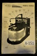
Air-Vac PCBRM-12 Wave Drag Soldering Machine Manual

http://www.industrialmanuals.com/airvac-pcbrm12-wave-drag-soldering-machine-manual-p-437.php

Air-Vac PCBRM-12 Wave Drag Soldering Machine Manual 
 
 
Air-Vac PCBRM-12 Wave Drag Soldering Machine Manual

This Manual Covers Models:
PCBRM-12

This Manual Includes:
Cleaning
Operation
Parts LIsts
Schematics
Dissasembly
Maintenance

This manual is about 17 pages

Adcock - Shipley Model 1E, Horizontal Milling Maintenance Manual Year (1966)

http://www.industrialmanuals.com/adcock-shipley-model-horizontal-milling-maintenance-manual-year-1966-p-2560.php 


Adcock - Shipley Model 1E, Horizontal Milling Maintenance Manual Year (1966) 

Adcock – Shipley Model 1E, Horizontal Milling Maintenance Manual
Year (1966)                 

This Manual Covers Models: 
1E
No. 1
This Manual Includes: 
Introduction
Capacity Chart
Specification
Installation Procedure
Operations Information (All Models)
Maintenance Information:
Spindles (All Models)
Lubrication (All Models)
L.S.L. Model
G Model
J Model
AH Model
Electrical Equipment (All Models)
Also included is an 8 Page Brochure No. N-43 that includes Specifications
Different Arrangements and Models Adcock Shipley from England


This Manual Has  51 Printed Pages.
Year 1966

Adaptive Motion Control Systems, IMC Edit, Controls and Tube Tool Offset Manual

http://www.industrialmanuals.com/adaptive-motion-control-systems-edit-controls-tube-tool-offset-manual-p-1867.php 


Adaptive Motion Control Systems, IMC Edit, Controls and Tube Tool Offset Manual 

Adaptive Motion Control Systems IMC Edit, Controls and Tube Tool Offset Manual Year (1993)  

This Manual Covers Models:
IMC Edit
This Manual Includes:
IMC Edit Page
Tube/Tool offset Page
Machine Control Axis Page
This Manual Has 46 Printed Pages.
Year 1993

Sunday, November 3, 2013

ACU-RITE MINI-Scale Digital Readout DRO Manual

http://www.industrialmanuals.com/acurite-miniscale-digital-readout-manual-p-21.php

ACU-RITE MINI-Scale Digital Readout DRO Manual 
 
 ACU-RITE Mini-Scale Assembly Digital Measuring System Installation and Instruction Manual:
 
This Manual Covers:I.M. Inventory A-163A
TABLE OF CONTENTS
Section Title Page No.
1. INTRODUCTION 1
2. PREPARATION 1
3. MOUNTING FOR LONGITUDINAL TRAVEL 2
3.1 Customer-Fabricated Mounting Hardware
3
3.2 Mounting and Alignment of Scale
Case 3
3.3 Mounting of Reading Head
3
3.4 Routing Cable From Reading Head to Console
4
4. MOUNTING FOR CROSS TRAVEL 5
5. MOUNTING FOR VERTICAL TRAVEL 5
6. DOVETAIL MOUNTING OPTION 6
7. ADDITIONAL SUPPORTS FOR SCALES OVER 24" 6
8. SYSTEM CHECKOUT 8
9. REPEATABILITY TEST 9
10. MINI-SCALE TROUBLESHOOTING GUIDE 10
LIST OF ILLUSTRATIONS
Figure Description Page No.
1. Mini-Scale Assembly (partially exploded view) .
2. Mini-Scale Assembly Dimensions
3. Two Basic Methods of Mounting Longitudinal Scale Assembly 2
4. Suggested Method of Providing Flat and True Mounting Surface , " 2
5. Methods of Lining Up Scale Case 3
6. Assembly Dimensions
(completely installed) 4 6A. Maximum Travel Limits 4
7. Two Methods of Mounting Cross Travel Scale Assembly 5
8. Universal Bracket, Mounting of Reading Head (Left Flange) 5
9. Universal Bracket, Mounting of Reading Head (Right Flange) 5
10. Suggested Method of Providing Mounting for SCale Case 6
11. Alternate Method of Providing Mounting for Scale Case on Z Axis 6
12. Typical Dimensions for Center Support Block, 7
13. Mounting With Adjustable Dovetail Mounting Block Kit '" 7 14A. Longitudinal Table Movement X Axis
15A. Cross Feed Table Movement Y Axis (-) 8 15B. Cross Feed Table Movement Y Axis (
16. A-R III Digital Readout Console (Top-Inside View) 8
17. Repeatability Test .. " 9
18. Reading Head Removal and Replacement 9
This Manual is 11 pages long & Mounting Data (during installation) ' . & Mounting Data (+) ,, 8 14B. Longitudinal Table Movement X Axis (-) ' 8 +) 8

Acu-Rite Mini Scale Linear Encoder System Manual

http://www.industrialmanuals.com/acurite-mini-scale-linear-encoder-system-manual-p-1861.php

Acu-Rite Mini Scale Linear Encoder System Manual 

Industrial Machinery Manuals Is Proud To Offer 1 Quality Bound Copy Of A:

Acu-Rite Mini Scale Linear Encoder System Installation Manual Year (1987)  

This Manual Covers Models:
Mini Scale

This Manual Includes:

Introduction
 For Digital and Vision Readout Systems
Preparation
Mounting for Longitudinal Travel
Mounting for Cross and Vertical Travel
Dovetail Mounting Option
Additional Supports for Scales over 24"
System Checkout
Repeatability Test
Mini-Scale Trouble shooting Guide
Illustrations 1 thru 18 of Assemblies


This Manual Has 13 Printed Pages.
Year 1987

Acu-Rite Mini Scale and Mate System Encoders, Reference Manual Year (1993)

http://www.industrialmanuals.com/acurite-mini-scale-mate-system-encoders-reference-manual-year-1993-p-2444.php 


Acu-Rite Mini Scale and Mate System Encoders, Reference Manual Year (1993) 

Acu-Rite Mini Scale and Mate System Encoders, Reference Manual Year (1993)     

This Manual Covers Models: 
Reference

This Manual Includes: 
I.M. Inventory # A-105SB
Introduction
Preparation:
Installation Planning
Typical Installations
Encoder Mounting dimensions and Methods
Other Mounting requirements

Encoder Installation:
Installation Steps and Checkout
Repeatability Test and Troubleshooting

Appendices:
ACU-RITE Encoder Specifications
Mini Scale Pin outs and Electrical Characteristics

This Manual Has 31 Printed Pages.
Year 1993

Acu-Rite MillPWR DRo, Programming & System Set-Up Manual Year (1995)

http://www.industrialmanuals.com/acurite-millpwr-programming-system-setup-manual-year-1995-p-2447.php 


Acu-Rite MillPWR DRo, Programming & System Set-Up Manual Year (1995) 

Acu-Rite MillPWR DRO, Programming & System Set-UP Manual Year (1995)      

This Manual Covers Models: 
MillPWR
DRO

This Manual Includes: 
I.M. Inventory # A-108SB
Two Axis Controller/three Axis Readout
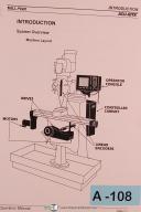
The complete MillPWR System includes: Motors, drives, precision glass scales, control cabinet, ballscrews, operator's console, special handcranks and all Mounting hardware.

System Setup Access Code
Edition E 387900-970
Introduction
DRO
Programming
Demonstration
Program Steps
Calculator
Setup
Troubleshooting Guide
Special Diagrams:
Schematic Block Diagrams
This Manual Has 102 Printed Pages.
Year November 1995
4 Large Diagrams