Monday, July 17, 2017

Warner & Swasey 2AC Chucking Automatic M-3200, Lots 1 to 41 incl, Service Manual

http://industrialmanuals.com/warner-swasey-chucking-automatic-m3200-lots-incl-service-manual-p-1816.php 


 Warner & Swasey 2AC Chucking Automatic M-3200, Lots 1 to 41 incl, Service Manual
Warner & Swasey 2AC Single Spindle Chucking Automatic Model M-3200, Lots 1 to 41 Service Manual      

This Manual Covers Models:
2AC
M-3200
Lots 1 to 41 Inclusive

This Manual Includes:
Machine Tool Data Sheet
Motors for Lots 1-3 Incl.
Single & Two Speed Machines Start Lot 15
For Two Speed Machines Start Lot 33
Miscellaneous Electrical Equipment Parts
Assembly Instructions-Adjustment of Limit Switches in Lever Support Assemblies
Assembly Instructions for Setting Geneva Limit Switch
No. 1AC (6") Single Spindle Automatic
No. 2AC (9") Single Spindle Automatic
Instructions for Timing Turret and Cross Slides
Instructions for Replacing Shear Pin
Instructions for Setting Indicators on Cross Slides and Pentagon Bar
Cross Slide Adjustments
Lubrications Specifications
Installation Instructions and Parts List for S-P Power Chucks and Cylinders Bulletin 12E
Instructions for Ordering Repair Parts
Index Brake – Service Manual , Series 4 Polyphase A.C. Brake
Warner Electric Brake Main Parts and Trouble Shooting
Autogap Installation Instructions
Machining Instructions for Gear, Sprocket or Pulley
Plates 10 thru 15 including Operators Panel
This Manual Has 89 Printed Pages.

Warner & Swasey 2AB single spindle Bar Automatic Operating Manual Year (1961)

http://industrialmanuals.com/warner-swasey-single-spindle-automatic-operating-manual-year-1961-p-1846.php 


 Warner & Swasey 2AB single spindle Bar Automatic Operating Manual Year (1961)
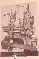
Warner & Swasey 2AB Single Spindle Bar Automatic Operating Instructions Manual Year (1961)         

This Manual Covers Models:
2AB
Single Spindle

This Manual Includes:
Setting Up
Operation
Tool Clearances
Standard Tool and Attachments
Preventive Maintenance

Data Sheet
Preventive Maintenance Check List
Installation
Lubrication and Coolant
Electrical Controls
Starting and Stopping the 2AB Machine
Selection of Speeds and Feeds
Hand Operation Control
Automatic Operation Control
Tapping and Threading Operations
Tooling and Setup
Standard Tool and Machine Data
Surface Speed Chart
Cutting Time Chart
Thread Cutting Time Chart
This Manual Has 70 Printed Pages.
Year 1961

Warner & Swasey 2AB Bar Automatic M-3380, Service Manual

http://industrialmanuals.com/warner-swasey-automatic-m3380-service-manual-p-1817.php

 Warner & Swasey 2AB Bar Automatic M-3380, Service Manual
Warner & Swasey 2AB Bar Automatic M-3380, Start Lot 1, Service Manual       

This Manual Covers Models:
2AB
M-3380
Starting Lot 1

This Manual Includes:
Preventive Maintenance
Turning Fact Sheet
Machine Tool Standard Data Sheet, C244192, C-279182, C-279183
Schematic Diagram of Hydraulic Clutches-Speed and Feed Dogs
Standard Gear Train & Hydraulic Diagram Start Lot 22
Schematic Diagram of Collet Chuck and Bar Feed Hydraulic Circuits
Instructions for Assembling No. 2AB M-3398 Bar Feed
Hydraulic Bar Feed
Instructions for Assembling 2AB Bar Feed M-3398 Start M-3380 Lot 45
No. 2AB (3in.) Bar Feed with Hyd. Operating Mechanism Start Lot 45, Hyd. Piping Hookup
Bar Feed & Collet Chuck Hyd. Piping diagram for Machine without Die Head Re-setter
Instructions on How To Change Collets, Draw Tube, Feed Finger , Tube & Filler Tube on M-3380 2AB Machine, D-244375
Dis-Assembly Instructions M-3398 2AB
2AB Timing Instructions (18 pages)
Lubrication and Specifications
Service Instructions for Bijur Automatic Lubrication System Type G
Maintenance and Service Instructions Fawick Magnetic Clutches Bulletin No. M-103-C
Instructions for Mounting and Using Manchester T-942 Holders
Repair Parts List for Stearns 87,000 Series Electric Disc Brakes
Dyna TorQ Brakes Model 308 Instruction Manual
Index Brake-Service Manual Series 4 Polyphase A.C. Brake
Dings Brakes Inc. Maintenance and Operating Instructions
Maintenance and Installation Instructions for Stearns Electric Disc Brakes
Threading Change Gear Charts
S-P Installation and Service Instructions for Self-Centering and Compensating Power Chucks

This Manual Has 129 Printed Pages.

Saturday, July 1, 2017

Warner & Swasey 2A, 3A and 4A, Turret Lathe Operation Parts & Electrical Manual

http://industrialmanuals.com/warner-swasey-turret-lathe-operation-parts-electrical-manual-p-5255.php 

Warner & Swasey 2A 3A 4A, Turret Lathe Operations and Parts Manual Year (1965)
 

This Manual Covers Models: 
2A
3A
4A
M-3470 Start Lot 4
M-3500 Start Lot 6
M-3550 Start Lot 2
M-3580 Start Lot 2
This Manual Includes:
Operating Instructions

Description and Operations of the Hydraulic Headstock
Hydraulic Circuit Details
Forward and Reverse Circuits
Brake Circuit
Shifting Circuit
Spindle Inching Circuit
Composite Diagram of Hydraulic Circuits

Installation
Introduction
Machine Data
Foundation
Moving the Turret Lathe
Cleaning
Electrical Connections
Lubrication

Major Turret Lathe Elements
Nomenclature of Major Turret Lathe Elements
One-piece Head and Bed
Headstock
Head End Gear Box
Square Turret
Cross Slide and Carriage Unit
Hexagon Turret and Saddle Unit
Repair Parts Section
Functionally illustrated Drawings showing Component Identification
Safety Manual for Turret Lathe Operators


This Manual Has 187 Printed Pages.
Year 1965

Warner & Swasey 2A Turret Lathe, M-510 Lot 12, Service and Parts Manual 1952

http://industrialmanuals.com/warner-swasey-turret-lathe-m510-service-parts-manual-1952-p-1830.php 


 Warner & Swasey 2A Turret Lathe, M-510 Lot 12, Service and Parts Manual 1952
Warner & Swasey 2A Heavy Duty Universal Turret Lathe , M-510 Lot 12, Service and Parts Manual Year (1952)       

This Manual Covers Models:
2-A
M-510
Lot 12

This Manual Includes:
Service Manual
Installation
Maintenance
Repair Parts
Erecting
Alignment
Feed Train
Pre-selector
Headstock
Cross Slide Carriage unit
Taper Attachment
Power Feed Compound Cross Slide
Hexagon Turret Saddle Unit
Bar Chucks and Bar Feeds
Cross Sliding Hexagon Turret
Lead Screw for Thread Cutting
Speed and Feed Chart
Repair Parts Section:
Plate 1 through Plate 43
Functional Illustrated Component Identification Diagrams
This Manual Has 97 Printed Pages.
Year 1952